 نمایش بزرگتر

LT1513-2IR
کد کالا: 12522
نو (جدید)
دستهبندی: آی سی های متفرقه
موجودی: این محصول در انبار موجود نیست
آی سی LT1513-2IR یک programmable-current/constant-voltage battery charger نوع SMD می باشد.
مستندات فنی و دیتاشیت
ویژگی های: LT1513-2IR
مشخصات کلی
اطلاعات بیشتر
آی سی LT1513-2IR یک programmable-current/constant-voltage battery charger نوع SMD می باشد.
تفاوت LT1513-2 با LT1513 در قابلیت تنظیم حداقل جریان شارژ است، در نوع LT1513 پین 3 برای اندازه گیری جریان شارژ استفاده می شود و روی 100mv تنظیم شده است به طوریکه وقتی جریان شارژ کمتر از حدی بشود که بر روی این مقاومت ولتاژ کمتر از 100mv ایجاد گردد، آی سی شارژ را قطع می کند.
ولی در آی سی نوع LT1513-2 محدودیت ولتاژ 100mv برداشته شده است و این مقدار بر روی 0 ولت تنظیم شده است، به این ترتیب می توان حداقل جریان شارژ آی سی را به صورت دلخواه تنظیم کرد.این کار با تنظیم مقاومت های متصل به این پایه، که به این ویژگی programmable current limit گفته شده است انجام می شود.
pin3 (Ifb) :
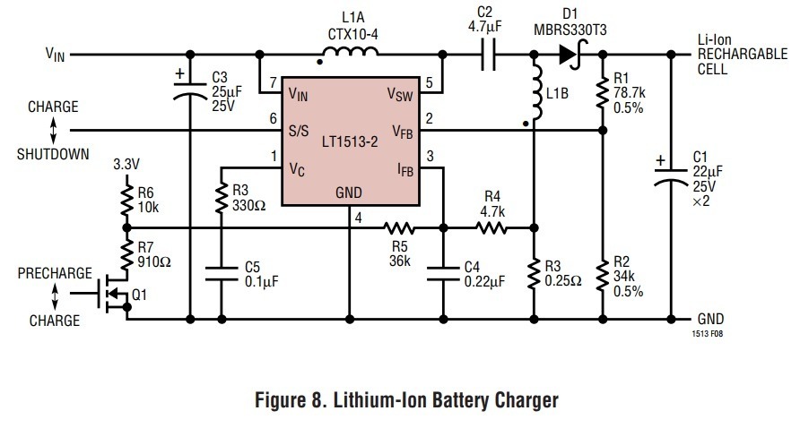
The current feedback pin is used to sense charging current. It is the input to a current sense amplifier that controls charging current when the battery voltage is below a programmed limit. During constant-current operation, the LT1513 IFB pin regulates at –100mV. Input resistance of this pin is 5kΩ, so filter resistance (R4, Figure 1) should be less than 50Ω. The 39Ω, 0.22µF filter shown in Figure 1 is used to convert the pulsating current in the sense resistor to a smooth DC current feedback signal. The LT1513-2 IFB pin regulates at 0mV to provide programmable current limit. The current through R5, Figure 5, is balanced by the current through R4, programming the maximum voltage across R3.
Programmed Charging Current LT1513-2:
Programmed Charging Current LT1513-2 charging current can be programmed with a DC voltage source or equivalent PWM signal, as shown in Figure 5. In constant-current mode, IFB acts as a virtual ground. The ISET voltage across R5 is balanced by the voltage across R4 in the ratio R4/R5. Charging current is given by: I V RR I R CHARGE ISET FBVOS = ( )( / )– 4 5 3 IFB input current is small and can normally be ignored, but IFB offset voltage must be considered if operating over a wide range of program currents. The voltage across R3 at maximum charge current can be increased to reduce offset errors at lower charge currents. In Figure 5, ISET from 0V to 5V corresponds to an ICHARGE of 0A to 1A +37/–62mA. C4 and R4 smooth the switch current waveform. During constant-current operation, the voltage feedback network loads the FB pin, which is held at VREF by the IFB amplifier. It is recommended that this load does not exceed 60µA to maintain a sharp constant voltage to constant current crossover characteristic. ICHARGE can also be controlled by a PWM input. Assuming the signal is a CMOS rail-to-rail output with a source impedance of less than a few hundred ohms, effective ISET is VCC multiplied by the PWM ratio. ICHARGE has good linearity over the entire 0% to 100% range.


@COMMENT_TITLE@
@COMMENT_COMMENT@